Manual.ly Logo

Voltcraft VC-13A Handleiding

4,0 · 2 Beoordelingen

PDF handleiding · 12 Pagina's

Nederlands

M: QW-35-FL
pagina

/ 12

Loading...
e150e37db53ef651200c1138b7cf35b312de page 5
c) Resistance measurement
Make sure that all the circuit parts, switches and components and other objects to be
measured are disconnected from the voltage and discharged at all times.
Proceed as follows to measure resistances:
• Select the measuring function “Ω” with the rotary switch .
• Connect the black measuring line to the COM socket (5) and the red measuring line to the socket “Ω” (6).
• Touch the two measuring tips to each other and wait until the pointer has stabilised. A value of approx.
0 Ohm must be displayed. In case of a deviation, adjust the pointer with the 0 Ohm calibration control (3)
to 0 Ohm. Always check this when changing the measuring range.
• Read off the measuring value on the scale “Ω”.
• In the “x1k” measurement range, multiply the displayed value by a factor of 1000 to get the measured
value e. g. 5 Ω (display) x 1000 = 5 x 1000 = 5 kΩ (measured value).
• In the “x10” measurement range, multiply the displayed value by a factor of 10 to get the measured value
e. g. 50 Ω (display) x 10 = 50 x 10 = 500 Ω (measured value).
• After completing the measurement, remove the measuring tips from the measuring circuit and switch the
multimeter off (rotary switch position: “OFF”).
d) Direct current measurement
Never exceed the max. permitted input values in the respective measuring ranges.
Current measuring operations are permissible only in circuits up to max. 300 V.
Proceed as follows to measure direct currents up to 250 mA/DC voltages:
• Select the measuring function “mA” with the rotary switch .
• Connect the black measuring line to the COM socket (5) and the red measuring line to the socket “mA” (6).
• Disconnect the object to be measured from the mains.
• Pay attention to the correct polarity (red = + / black = -) and connect the two measuring tips in series with
the measuring object (battery, circuit, etc.).
• In the case of a pole reversal, the needle deects in the negative direction. This could damage the meter
mechanism. Stop the measurement at once and repeat the measurement with the correct polarity.
• Read off the measuring value on the scale “mA”.
• Disconnect the measured object from the mains and remove the measuring tips from the measuring
circuit after the measurement is completed. Switch off the multimeter (rotary switch position “OFF”).
e) Attenuation measurement in dBm
The multimeter enables absolute “dB” measuring in circuits with an impedance of 600 Ohm. Measurements
are made in the “10 V~” range. 0 dB = 1 mW (0.775 V).
Proceed as follows for the measurement:
• With the rotary switch, select the measuring range “10 V~“.
• Connect the black measuring line to the COM socket (5) and the red measuring line to the socket “V” (6).
• Now connect the two measuring probes in parallel to the object to be measured (generator, switch, etc.).
• Read off the measured value on the scale “dB”. Read the voltage on the scale “AC10V”.
• If signals with a direct voltage ratio are to be measured, a capacitor of >0.1nF must be connected in
series to the measuring lines (decoupling).
• After completing the measurement, remove the measuring tips from the measuring circuit and switch the
multimeter off (rotary switch position: “OFF”).
f) Battery test
The multimeter tests 1.5 V or 9 V batteries with a low load. This prevents faulty measurements during
open-circuit operation and gives signicant clues to the battery condition.
"REPLACE" indicates that the battery must be replaced.
"?" indicates that the battery can still be used only for low power consumer loads.
"GOOD" indicates that the battery is OK.
To test the batteries, proceed as follows:
• With the rotary switch select the measuring function “BAT” and the measuring range 1.5 V or 9 V.
• Connect the black measuring line to the COM socket (5) and the red measuring line to the socket “V” (6).
• Pay attention to the correct polarity (red = + / black = -) and connect the two measuring tips to the
battery.
• In the case of a pole reversal, the needle deects in the negative direction. This could damage the meter
mechanism. Stop the measurement at once and repeat the measurement with the correct polarity.
• Read off the measured value on the scale “BAT”.
• After completing the measurement, remove the measuring tips from the measuring circuit and switch the
multimeter off (rotary switch position: “OFF”).
CLEANING AND MAINTENANCE
General information
To ensure the accuracy of the multimeter over an extended period of time, it should be calibrated once a
year.
Information on changing the battery and fuse appears below.
Regularly check the technical safety of the device and the measuring cables, e.g. for
damage to the housing or crimping, etc.
Never operate the meter when it is open. ! RISK OF FATAL INJURY!
EXPLANATION OF SYMBOLS AND SIGNS
Overload, the resistance measuring range was exceeded
Symbol for the built-in battery data
Symbol for the built-in fuse
OFF Switch position OFF
COM Measurement reference potential, - for DC
VmAΩ Measurement input for measurement potential, + for DC
AC Symbol for alternating current
DC Symbol for direct current
V Volt (unit of electric voltage)
mA Milliampere (unit of electric current, exp.-3)
Ω Ohm (unit of electrical resistance)
x10 The resistance value read must be multiplied by 10
x1k The resistance value read must be multiplied by 1000
dB
Decibels, attenuation in the 10 V AC voltage measurement circuit
(0 dB = 1 mW/600 Ohm = 0.775 V)
BAT Battery test
9 V/1.5 V Measurement range for batteries with 9 V or 1.5 V nominal voltage
REPLACE The tested battery must be replaced
? The tested battery should be replaced as soon as possible
GOOD The tested battery can be used
START-UP
Before you can work with the measuring device in the resistance measurement range, you must
rst insert the enclosed battery. Insert the battery as described in the chapter “Cleaning and Mainte-
nance”.
Rotary switch (4)
• The individual measuring functions and ranges can be set using the rotary switch.
• If the rotary switch is set to “OFF”, the measuring device is switched off.
• Always turn the meter off when it is not in use.
• An automatic cut-off does not occur in the resistance range.
WEIGHING
Do not exceed the maximum permitted input values under any circumstances. Never
touch circuits or parts of circuits when they may contain voltages greater than
33 V/ACrms or 70 V/DC! Risk of fatal injury! Before every measurement, check the
meter and the connected measuring leads for damage such as cuts, cracks or pinches.
Remove defective measuring leads immediately and replace them with new measuring
cables. Defective measuring leads must no longer be used. ! Risk of fatal injury!
Before changing the measuring range, the test probes have to be removed from the
measured object.
Always start each measurement with the largest measuring range. Then gradually
change to a smaller one to achieve an exact measured result. The best precision occurs
in the mid-scale range (scale range ca. 70° to 110°).
The measuring results at the rotary switch correspond to the scale end value. For reading, always select
the corresponding value (e.g. scale 10 for the measuring range 10).
a) Zero adjustment
Before each measurement, adjust the zero position with the calibration screw (2) (scale value 0 V). There
must be no measuring signal on the measuring lines.
b) Measuring AC and DC voltages
Do not exceed the maximum permitted input values under any circumstances.
Proceed as follows to measure direct current (DC) voltages:
• Select the measuring function V with the rotary switch .
• Connect the black measuring line to the COM socket (5) and the red measuring line to the V socket (6).
• Pay attention to the correct polarity (red = + / black = -) and connect the two measuring tips in parallel to
the object to be measured (battery, circuit, etc.).
• In the case of a pole reversal, the needle deects in the negative direction. This could damage the meter
mechanism. Stop the measurement at once and repeat the measurement with the correct polarity.
• Read off the measured value on the scale “V”.
DC V range V scale for reading Multiplier
2.5 0 - 250 0.01
10 0 - 10 1
50 0 - 50 1
250 0 - 250 1
300 0 - 300 1
• After completing the measurement, remove the measuring tips from the measuring circuit and switch the
multimeter off (rotary switch position: “OFF”).
Proceed as follows to measure AC voltages:
• Select the measuring function V with the rotary switch .
• Connect the black measuring line to the COM socket (5) and the red measuring line to the V socket (6).
• Now connect the two measuring probes in parallel to the object to be measured (generator, switch etc.).
• Read off the measured value on the scale “V”.
• After completing the measurement, remove the measuring tips from the measuring circuit and switch the
multimeter off (rotary switch position: “OFF”).

Chat met je Voltcraft VC-13A-handleiding via AI

Krijg direct AI-antwoorden uit je Voltcraft VC-13A-handleiding

Vraag alles over Voltcraft VC-13A. Antwoorden komen uit deze handleiding, met de pagina's waarop ze zijn gebaseerd.

VC-13A Onderhoudsschema

Herinner mij wanneer onderhoud nodig is
Jaarlijks
Kalibreer de multimeter

Om nauwkeurigheid over een langere periode te waarborgen, adviseert de handleiding het apparaat jaarlijks te kalibreren.

Regelmatig
Controleer apparaat en kabels op schade

Controleer regelmatig de technische veiligheid van het apparaat en de meetkabels op behuizingsschade of knikken.

Gratis onderhoudsherinneringen

Afgestemd op uw aankoopdatum. Altijd gratis, op elk moment afmelden.

Door te verzenden gaat u akkoord met het privacybeleid. U kunt zich met een klik afmelden in elke e-mail.
M: qwen/qwen3.8-flash

Stel eenVraag

0/1000

Beveel je VC-13A aan?

Ja Nee
0
User Pic

anderson47

6 maanden geleden

Is het veilig om een langzamere zekering met een hogere spanningswaarde te gebruiken als de originele snelle zekering niet beschikbaar is?

0
User Pic

Manual.ly

6 maanden geleden

Hoewel het gebruik van een vervangende zekering het apparaat tijdelijk kan laten werken, wordt dit niet aanbevolen voor de lange termijn veiligheid. De oorspronkelijke zekeringwaarde zorgt voor de juiste bescherming tegen overstroom. Het gebruik van een zekering met een hogere spanning of langzamere reactie kan de veiligheid in geval van een elektrische storing in gevaar brengen. We adviseren om de juiste 500V snelwerkende zekering te vinden voordat u het apparaat regelmatig gebruikt.

M: QW-35-FL
M: QW-35-FL
0
User Pic

Nikki Ross

4 maanden geleden

Maakt de compacte maat en goed leesbare schaal dit gereedschap geschikt voor beginners?

M: QW-35-FL

Veelgestelde Vragen

A

Nee, gebruik de multimeter niet in vochtige kamers, onder hoge luchtvochtigheid of wanneer het nat is. Vocht kan de veiligheid in gevaar brengen en het apparaat beschadigen.

Is dit antwoord nuttig?

A

Het vereist één Mignon-batterij, specifiek Type AA (UM3, LR6 of equivalent) met een spanning van 1,5 V.

Is dit antwoord nuttig?

A

Sluit de sondes samen, wacht tot de naald tot rust komt en stel de 0-Ohm-regeling in op nul voordat u het onderdeel meet.

Is dit antwoord nuttig?

A

Ja, het is geclassificeerd als CAT III tot 300 V, waardoor het geschikt is voor huishoudelijke elektrische installaties en algemene hobbytaken.

Is dit antwoord nuttig?

A

Stop onmiddellijk, koppel de sondes los en controleer uw polariteit. Draai de rode en zwarte leidingen om om de verbinding te corrigeren.

Is dit antwoord nuttig?

A

Nee, ongeautoriseerde wijziging of conversie is strikt verboden om veiligheids- en goedkeuringsredenen (CE).

Is dit antwoord nuttig?

A

Om de nauwkeurigheid in de tijd te garanderen, moet het apparaat ten minste één keer per jaar worden gekalibreerd.

Is dit antwoord nuttig?

M: QW-35-FL

Voordelen en Nadelen

Voordelen

  • Schokabsorberend wijzerinstrument werkt in elke oriëntatie
  • Bevat ingebouwde batterijtest voor 1,5 V en 9 V cellen
  • Metingscategorie III geclassificeerd tot 300 V voor veilig gebouwinstallatiewerk
  • Keramische zekering beschermt het mA-stroombereik tegen overbelasting
  • Kalibratieschroef stelt precieze nulling mogelijk voor gebruik
VS

Nadelen

  • Geen automatische uitschakelfunctie in weerstandsmodus
  • Vereist handmatige nulling voor nauwkeurige aflezingen
  • Niet geschikt voor het meten van spanningen hoger dan 300 V veilig
  • Kan niet worden gebruikt in explosieve atmosferen of vochtige kamers
  • Handbediening vereist gebruiker aandacht voor polariteit en bereiken
M: QW-35-FL

Product Specificatie

Meetbereik

max. 300 V, max. 2 MΩ

Inhoud verpakking

Testdraden

M: QW-35-FL

Product Beschrijving

Voltcraft VC-13A Analoge Multimeter Beoordeling

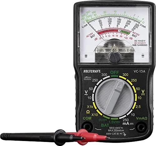
De Voltcraft VC-13A Analoge Multimeter is een robuust en betrouwbaar hulpmiddel ontworpen voor zowel hobbyisten als professionals die nauwkeurige elektrische metingen vereisen in een draagbaar formaat. Dit apparaat beschikt over een schokabsorberend wijzerinstrument dat aflezingen in elke bedrijfspositie toelaat, waardoor het ideaal is voor krappe ruimtes of ongemakkelijke hoeken waar digitale displays moeilijk te lezen zijn. De multimeter ondersteunt Metingscategorie III tot 300 V, wat veiligheid tijdens gebruik in gebouweninstallaties zoals stopcontacten en sub-verdelingen garandeert.

Uitgerust met een rotatieschakelaar kunnen gebruikers eenvoudig kiezen tussen verschillende functies waaronder gelijkstroom (DC), wisselstroom (AC), weerstand en dempingsmetingen. Het mA-stroombereik wordt beschermd door een keramische zekering tegen overbelasting, wat een extra veiligheidslaag toevoegt. Voor elke meting kan de schaalswijzer worden aangepast met de kalibratieschroef om nauwkeurigheid te garanderen en leesfouten te voorkomen. Het apparaat bevat ook een speciale batterijtestfunctie voor 1,5 V en 9 V-batterijen, die duidelijke indicatoren zoals "GOED", "?" of "VERVANGEN" biedt om de batterijstatus te beoordelen zonder externe testers te gebruiken.

Veiligheid staat bij dit apparaat op de eerste plaats. Het voldoet aan CE-normen en beschikt over dubbele isolatie. Gebruikers wordt geadviseerd spanningen boven 33 V AC of 70 V DC niet te meten tenzij ze getrainde professionals zijn. Het apparaat mag nooit worden bediend met een open behuizing of ontbrekende batterijdeksel om dodelijke elektrische schokken te voorkomen. Bovendien mag het niet worden gebruikt tijdens onweersbuien of in omgevingen met brandbare gassen. Regelmatig onderhoud, zoals jaarlijkse kalibratie en controle op beschadigde leidingen, zorgt voor langetermijnbetrouwbaarheid. Het pakket bevat de multimeter, testleidingen, een AA-batterij en uitgebreide instructies online beschikbaar.

Belangrijke Kenmerken en Gebruiksnotities

Deze analoge meter blinkt uit in eenvoud en duurzaamheid. Het grote schaalbeeld maakt het gemakkelijk om trends en fluctuaties in real-time te observeren. Bij het meten van weerstand moet u de meter nollen door de sondes kort te sluiten en de 0-Ohm-regeling aan te passen. Begin altijd met metingen op het hoogste bereik en werk naar beneden voor betere precisie. Houd het apparaat droog en weg van sterke magnetische velden om vervormde aflezingen te vermijden.

M: QW-35-FL

© Copyright 2026 Manual.ly